Understanding Precision Testing: Q&As on Kelvin Test and Kelvin Pins
2026-03-17
Understanding Precision Testing: Q&As on Kelvin Test and Kelvin Pins
As electronic devices move toward higher performance and lower power consumption, measurement tolerances have narrowed to the micro-ohm (µΩ) range. At this level, conventional two-wire methods systematically introduce measurement offsets by incorporating lead impedance and probe contact resistance into the measurement path. In high-current or precision semiconductor testing, these deviations directly impact yield, characterization accuracy, and product reliability.
To eliminate these parasitic resistances, Kelvin testing (4-wire measurement) has become the industry standard for ensuring high-accuracy results. How does the Kelvin Test achieve true-potential measurement? This Q&A examines the mechanics and advantages of this precision technology.
Q1: What is the Kelvin Test? What is its primary purpose?
The Kelvin Test is a high-accuracy measurement technique, also known as 4-wire measurement. Its core principle is the complete separation of the Current Drive (Force) and Voltage Measurement (Sense) paths. By utilizing an independent high-impedance sense circuit, the voltage drop across the test leads and contact points is effectively excluded from the measurement.
This technology is critical for low-impedance electrical characterization, such as IC conduction resistance, PMIC efficiency, and high-speed, high-current testing. When the resistance of the DUT is comparable to or smaller than the probe contact resistance, traditional 2-wire measurement fails as it aggregates these "non-target resistances," resulting in errors that exceed allowable tolerances.
Furthermore, in high-current path measurements, the voltage drop generated by minute resistance can cause severe data distortion. Therefore, in automated measurement environments where data stability and reproducibility are critical, the Kelvin Test must be employed to exclude variables arising from probe oxidation or pressure changes, ensuring measurement results accurately reflect the true state of the DUT.
Q2: What is a Kelvin Pin? How does it differ from a standard probe?
In a conventional two-wire setup, current and voltage share the same path, so lead impedance and probe contact resistance are included in the reading. For low-impedance devices, this can introduce significant measurement error, and the results may drift as contact pressure or probe condition changes.
A Kelvin pin separates these functions into two independent paths: the force line delivers current, while the sense line measures voltage only. Because the sense terminal operates at extremely high impedance and carries virtually no current, there is no additional voltage drop along the measurement path. The probe can therefore capture the true voltage directly at the DUT, making Kelvin configurations well suited for mΩ measurements and high-current test environments.
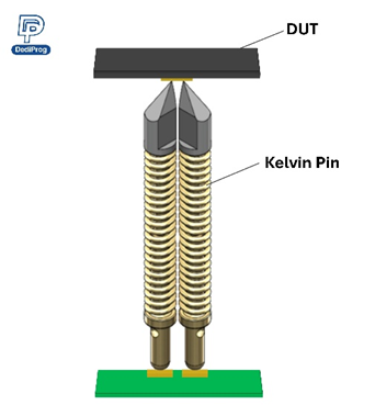
Additionally, Kelvin pin heads are typically more compact and precisely aligned. For example, DediProg’s dual-pin Kelvin contacts can be designed with tip spacing as fine as 70 µm, enabling accurate, stable contact on fine-pitch leads, high-density pads, and compact IC packages.
Q3: How are Kelvin Pins applied in FT fixtures?
In FT (Final Test) fixtures, Kelvin Pins typically provide two contact points on the same pad or solder ball: one for power supply and one for measurement, ensuring that lead or contact impedance does not affect accuracy.
Q4: Which packages are Kelvin pins suitable for?
Kelvin pins are commonly used with BGA, LGA, QFN, and CSP packages—especially in applications with fine pitch or higher current requirements, where accurate low-resistance measurement and stable contact are essential.
Q5: What are the equipment requirements for using Kelvin pins?
The measurement instrument must support four-wire measurement mode—such as a digital multimeter (DMM) or source measure unit (SMU)—with separate Force and Sense terminals for independent connections.
Q6: Does DediProg offer Kelvin pin sockets or custom Kelvin pin services?
Yes. DediProg provides comprehensive Kelvin pin and test socket solutions, covering everything from fine-pitch probe selection to the custom design and manufacturing of high-precision sockets. With reliable quality and responsive lead times, we help customers accelerate their development and validation processes.
Read More:
Understanding PCR: Applications, Advantages, and Maintenance FAQs
The Engineer’s Guide to Pogo Pins: 15 Must-Know Q&As
How to Choose IC Test Interfaces? PCR vs. Pogo Pin: Comparison of Electrical Performance, Lifespan, and Cost
Burn-in Testing and Burn-in Sockets: FAQs Answered
Explore More:
Pogo Pin
PCR (Pressure Conductive Silicone Rubber)
Burn-in Socket
PCR Socket
PCB/R Socket
Final Test Socket
Open Top Socket
DDR5 Module Test Socket
DDR4 Module Test Socket
Not sure which testing solution fits your needs? Please contact us for a free evaluation.
 |  |  |  |

E-mail: sales@dediprog.com